3.5 The Michelson Interferometer
Learning Objectives
By the end of this section, you will be able to:
- Explain changes in fringes observed with a Michelson interferometer caused by mirror movements
- Explain changes in fringes observed with a Michelson interferometer caused by changes in medium
The Michelson interferometer (invented by the American physicist Albert A. Michelson, 1852–1931) is a precision instrument that produces interference fringes by splitting a light beam into two parts and then recombining them after they have traveled different optical paths. Figure 3.16 depicts the interferometer and the path of a light beam from a single point on the extended source S, which is a ground-glass plate that diffuses the light from a monochromatic lamp of wavelength . The beam strikes the half-silvered mirror M, where half of it is reflected to the side and half passes through the mirror. The reflected light travels to the movable plane mirror , where it is reflected back through M to the observer. The transmitted half of the original beam is reflected back by the stationary mirror and then toward the observer by M.
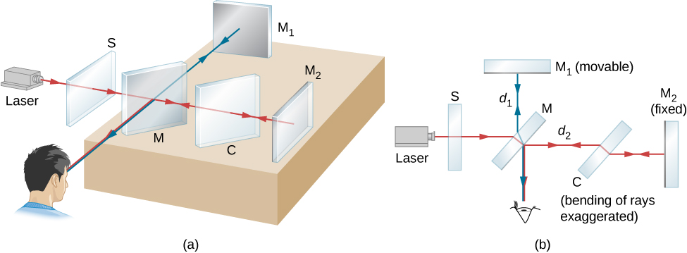
Because both beams originate from the same point on the source, they are coherent and therefore interfere. Notice from the figure that one beam passes through M three times and the other only once. To ensure that both beams traverse the same thickness of glass, a compensator plate C of transparent glass is placed in the arm containing . This plate is a duplicate of M (without the silvering) and is usually cut from the same piece of glass used to produce M. With the compensator in place, any phase difference between the two beams is due solely to the difference in the distances they travel.
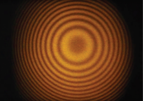
The path difference of the two beams when they recombine is , where is the distance between M and , and is the distance between M and . Suppose this path difference is an integer number of wavelengths . Then, constructive interference occurs and a bright image of the point on the source is seen at the observer. Now the light from any other point on the source whose two beams have this same path difference also undergoes constructive interference and produces a bright image. The collection of these point images is a bright fringe corresponding to a path difference of (Figure 3.17). When is moved a distance , this path difference changes by , and each fringe moves to the position previously occupied by an adjacent fringe. Consequently, by counting the number of fringes m passing a given point as is moved, an observer can measure minute displacements that are accurate to a fraction of a wavelength, as shown by the relation
Example 3.5
Precise Distance Measurements by Michelson Interferometer
A red laser light of wavelength 630 nm is used in a Michelson interferometer. While keeping the mirror fixed, mirror is moved. The fringes are found to move past a fixed cross-hair in the viewer. Find the distance the mirror is moved for a single fringe to move past the reference line.Strategy
Refer to Figure 3.16 for the geometry. We use the result of the Michelson interferometer interference condition to find the distance moved, .Solution
For a 630-nm red laser light, and for each fringe crossing , the distance traveled by if you keep fixed isSignificance
An important application of this measurement is the definition of the standard meter. As mentioned in Units and Measurement, the length of the standard meter was once defined as the mirror displacement in a Michelson interferometer corresponding to 1,650,763.73 wavelengths of the particular fringe of krypton-86 in a gas discharge tube.Example 3.6
Measuring the Refractive Index of a Gas
In one arm of a Michelson interferometer, a glass chamber is placed with attachments for evacuating the inside and putting gases in it. The space inside the container is 2 cm wide. Initially, the container is empty. As gas is slowly let into the chamber, you observe that dark fringes move past a reference line in the field of observation. By the time the chamber is filled to the desired pressure, you have counted 122 fringes move past the reference line. The wavelength of the light used is 632.8 nm. What is the refractive index of this gas?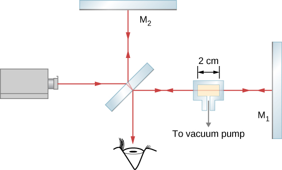
Strategy
The fringes observed compose the difference between the number of wavelengths that fit within the empty chamber (vacuum) and the number of wavelengths that fit within the same chamber when it is gas-filled. The wavelength in the filled chamber is shorter by a factor of n, the index of refraction.Solution
The ray travels a distance to the right through the glass chamber and another distance t to the left upon reflection. The total travel is . When empty, the number of wavelengths that fit in this chamber iswhere is the wavelength in vacuum of the light used. In any other medium, the wavelength is and the number of wavelengths that fit in the gas-filled chamber is
The number of fringes observed in the transition is
Solving for gives
and .
Significance
The indices of refraction for gases are so close to that of vacuum, that we normally consider them equal to 1. The difference between 1 and 1.0019 is so small that measuring it requires a correspondingly sensitive technique such as interferometry. We cannot, for example, hope to measure this value using techniques based simply on Snell’s law.Check Your Understanding 3.3
Although m, the number of fringes observed, is an integer, which is often regarded as having zero uncertainty, in practical terms, it is all too easy to lose track when counting fringes. In Example 3.6, if you estimate that you might have missed as many as five fringes when you reported fringes, (a) is the value for the index of refraction worked out in Example 3.6 too large or too small? (b) By how much?
Problem-Solving Strategy
Wave Optics
Step 1. Examine the situation to determine that interference is involved. Identify whether slits, thin films, or interferometers are considered in the problem.
Step 2. If slits are involved, note that diffraction gratings and double slits produce very similar interference patterns, but that gratings have narrower (sharper) maxima. Single-slit patterns are characterized by a large central maximum and smaller maxima to the sides.
Step 3. If thin-film interference or an interferometer is involved, take note of the path length difference between the two rays that interfere. Be certain to use the wavelength in the medium involved, since it differs from the wavelength in vacuum. Note also that there is an additional phase shift when light reflects from a medium with a greater index of refraction.
Step 4. Identify exactly what needs to be determined in the problem (identify the unknowns). A written list is useful. Draw a diagram of the situation. Labeling the diagram is useful.
Step 5. Make a list of what is given or can be inferred from the problem as stated (identify the knowns).
Step 6. Solve the appropriate equation for the quantity to be determined (the unknown) and enter the knowns. Slits, gratings, and the Rayleigh limit involve equations.
Step 7. For thin-film interference, you have constructive interference for a total shift that is an integral number of wavelengths. You have destructive interference for a total shift of a half-integral number of wavelengths. Always keep in mind that crest to crest is constructive whereas crest to trough is destructive.
Step 8. Check to see if the answer is reasonable: Does it make sense? Angles in interference patterns cannot be greater than , for example.