Challenge Problems
Some camera flashes use flash tubes that require a high voltage. They obtain a high voltage by charging capacitors in parallel and then internally changing the connections of the capacitors to place them in series. Consider a circuit that uses four AAA batteries connected in series to charge six 10-mF capacitors through an equivalent resistance of . The connections are then switched internally to place the capacitors in series. The capacitors discharge through a lamp with a resistance of . (a) What is the RC time constant and the initial current out of the batteries while they are connected in parallel? (b) How long does it take for the capacitors to charge to of the terminal voltages of the batteries? (c) What is the RC time constant and the initial current of the capacitors connected in series assuming it discharges at of full charge? (d) How long does it take the current to decrease to of the initial value?
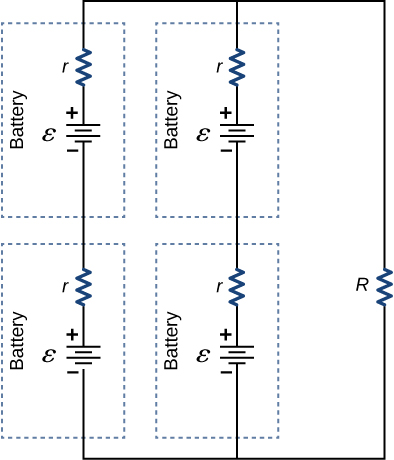
Consider the circuit shown below. Each battery has an emf of 1.50 V and an internal resistance of (a) What is the current through the external resistor, which has a resistance of 10.00 ohms? (b) What is the terminal voltage of each battery?
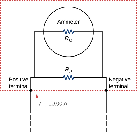
Analog meters use a galvanometer, which essentially consists of a coil of wire with a small resistance and a pointer with a scale attached. When current runs through the coil, the pointer turns; the amount the pointer turns is proportional to the amount of current running through the coil. Galvanometers can be used to make an ammeter if a resistor is placed in parallel with the galvanometer. Consider a galvanometer that has a resistance of and gives a full scale reading when a current runs through it. The galvanometer is to be used to make an ammeter that has a full scale reading of 10.00 A, as shown below. Recall that an ammeter is connected in series with the circuit of interest, so all 10 A must run through the meter. (a) What is the current through the parallel resistor in the meter? (b) What is the voltage across the parallel resistor? (c) What is the resistance of the series resistor?
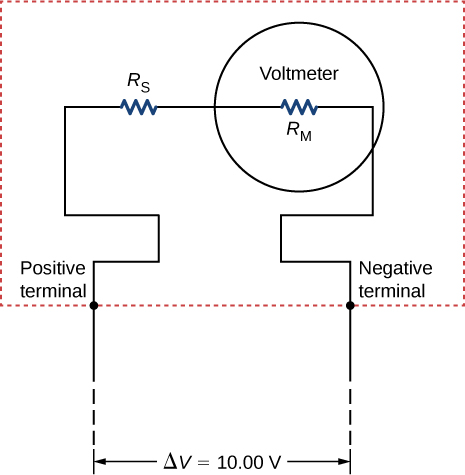
Analog meters use a galvanometer, which essentially consists of a coil of wire with a small resistance and a pointer with a scale attached. When current runs through the coil, the point turns; the amount the pointer turns is proportional to the amount of current running through the coil. Galvanometers can be used to make a voltmeter if a resistor is placed in series with the galvanometer. Consider a galvanometer that has a resistance of and gives a full scale reading when a current runs through it. The galvanometer is to be used to make an voltmeter that has a full scale reading of 10.00 V, as shown below. Recall that a voltmeter is connected in parallel with the component of interest, so the meter must have a high resistance or it will change the current running through the component. (a) What is the potential drop across the series resistor in the meter? (b) What is the resistance of the parallel resistor?
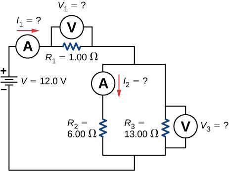
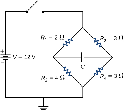
Consider the circuit shown below. Find
Consider the circuit below. (a) What is the RC time constant of the circuit? (b) What is the initial current in the circuit once the switch is closed? (c) How much time passes between the instant the switch is closed and the time the current has reached half of the initial current?
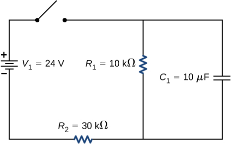
Consider the circuit below. (a) What is the initial current through resistor when the switch is closed? (b) What is the current through resistor when the capacitor is fully charged, long after the switch is closed? (c) What happens if the switch is opened after it has been closed for some time? (d) If the switch has been closed for a time period long enough for the capacitor to become fully charged, and then the switch is opened, how long before the current through resistor reaches half of its initial value?
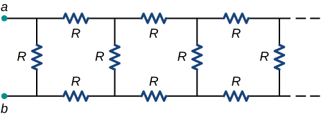
Consider the infinitely long chain of resistors shown below. What is the resistance between terminals a and b?
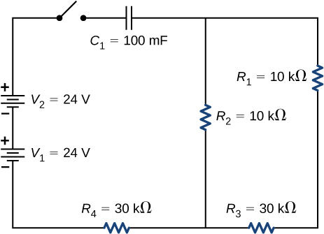
Consider the circuit below. The capacitor has a capacitance of 10 mF. The switch is closed and after a long time the capacitor is fully charged. (a) What is the current through each resistor a long time after the switch is closed? (b) What is the voltage across each resistor a long time after the switch is closed? (c) What is the voltage across the capacitor a long time after the switch is closed? (d) What is the charge on the capacitor a long time after the switch is closed? (e) The switch is then opened. The capacitor discharges through the resistors. How long from the time before the current drops to one fifth of the initial value?
A 120-V immersion heater consists of a coil of wire that is placed in a cup to boil the water. The heater can boil one cup of water in 180.00 seconds. You buy one to use in your dorm room, but you are worried that you will overload the circuit and trip the 15.00-A, 120-V circuit breaker, which supplies your dorm room. In your dorm room, you have four 100.00-W incandescent lamps and a 1500.00-W space heater. (a) What is the power rating of the immersion heater? (b) Will it trip the breaker when everything is turned on? (c) If it you replace the incandescent bulbs with 18.00-W LED, will the breaker trip when everything is turned on?
Find the resistance that must be placed in series with a galvanometer having a sensitivity (the same as the one discussed in the text) to allow it to be used as a voltmeter with a 3000-V full-scale reading. Include a circuit diagram with your solution.
Find the resistance that must be placed in parallel with a galvanometer having a 1.00-mA sensitivity (the same as the one discussed in the text) to allow it to be used as an ammeter with a 25.0-A full-scale reading. Include a circuit diagram with your solution.