14.6 Bernoulli’s Equation
Learning Objectives
By the end of this section, you will be able to:
- Explain the terms in Bernoulli’s equation
- Explain how Bernoulli’s equation is related to the conservation of energy
- Describe how to derive Bernoulli’s principle from Bernoulli’s equation
- Perform calculations using Bernoulli’s principle
- Describe some applications of Bernoulli’s principle
As we showed in Figure 14.27, when a fluid flows into a narrower channel, its speed increases. That means its kinetic energy also increases. The increased kinetic energy comes from the net work done on the fluid to push it into the channel. Also, if the fluid changes vertical position, work is done on the fluid by the gravitational force.
A pressure difference occurs when the channel narrows. This pressure difference results in a net force on the fluid because the pressure times the area equals the force, and this net force does work. Recall the work-energy theorem,
The net work done increases the fluid’s kinetic energy. As a result, the pressure drops in a rapidly moving fluid whether or not the fluid is confined to a tube.
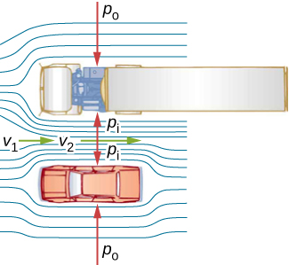
There are many common examples of pressure dropping in rapidly moving fluids. For instance, shower curtains have a disagreeable habit of bulging into the shower stall when the shower is on. The reason is that the high-velocity stream of water and air creates a region of lower pressure inside the shower, whereas the pressure on the other side remains at the standard atmospheric pressure. This pressure difference results in a net force, pushing the curtain inward. Similarly, when a car passes a truck on the highway, the two vehicles seem to pull toward each other. The reason is the same: The high velocity of the air between the car and the truck creates a region of lower pressure between the vehicles, and they are pushed together by greater pressure on the outside (Figure 14.29). This effect was observed as far back as the mid-1800s, when it was found that trains passing in opposite directions tipped precariously toward one another.
Energy Conservation and Bernoulli’s Equation
The application of the principle of conservation of energy to frictionless laminar flow leads to a very useful relation between pressure and flow speed in a fluid. This relation is called Bernoulli’s equation, named after Daniel Bernoulli (1700–1782), who published his studies on fluid motion in his book Hydrodynamica (1738).
Consider an incompressible fluid flowing through a pipe that has a varying diameter and height, as shown in Figure 14.30. Subscripts 1 and 2 in the figure denote two locations along the pipe and illustrate the relationships between the areas of the cross sections A, the speed of flow v, the height from ground y, and the pressure p at each point. We assume here that the density at the two points is the same—therefore, density is denoted by without any subscripts—and since the fluid is incompressible, the shaded volumes must be equal.
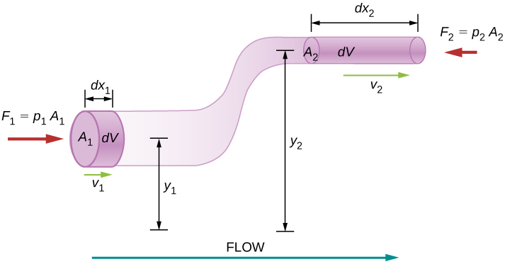
We also assume that there are no viscous forces in the fluid, so the energy of any part of the fluid will be conserved. To derive Bernoulli’s equation, we first calculate the work that was done on the fluid:
The work done was due to the conservative force of gravity and the change in the kinetic energy of the fluid. The change in the kinetic energy of the fluid is equal to
The change in potential energy is
The energy equation then becomes
Rearranging the equation gives Bernoulli’s equation:
This relation states that the mechanical energy of any part of the fluid changes as a result of the work done by the fluid external to that part, due to varying pressure along the way. Since the two points were chosen arbitrarily, we can write Bernoulli’s equation more generally as a conservation principle along the flow.
Bernoulli’s Equation
For an incompressible, frictionless fluid, the combination of pressure and the sum of kinetic and potential energy densities is constant not only over time, but also along a streamline:
A special note must be made here of the fact that in a dynamic situation, the pressures at the same height in different parts of the fluid may be different if they have different speeds of flow.
Analyzing Bernoulli’s Equation
According to Bernoulli’s equation, if we follow a small volume of fluid along its path, various quantities in the sum may change, but the total remains constant. Bernoulli’s equation is, in fact, just a convenient statement of conservation of energy for an incompressible fluid in the absence of friction.
The general form of Bernoulli’s equation has three terms in it, and it is broadly applicable. To understand it better, let us consider some specific situations that simplify and illustrate its use and meaning.
Bernoulli’s equation for static fluids
First consider the very simple situation where the fluid is static—that is, Bernoulli’s equation in that case is
We can further simplify the equation by setting (Any height can be chosen for a reference height of zero, as is often done for other situations involving gravitational force, making all other heights relative.) In this case, we get
This equation tells us that, in static fluids, pressure increases with depth. As we go from point 1 to point 2 in the fluid, the depth increases by , and consequently, is greater than by an amount . In the very simplest case, is zero at the top of the fluid, and we get the familiar relationship . and Thus, Bernoulli’s equation confirms the fact that the pressure change due to the weight of a fluid is . Although we introduce Bernoulli’s equation for fluid motion, it includes much of what we studied for static fluids earlier.
Bernoulli’s principle
Suppose a fluid is moving but its depth is constant—that is, . Under this condition, Bernoulli’s equation becomes
Situations in which fluid flows at a constant depth are so common that this equation is often also called Bernoulli’s principle, which is simply Bernoulli’s equation for fluids at constant depth. (Note again that this applies to a small volume of fluid as we follow it along its path.) Bernoulli’s principle reinforces the fact that pressure drops as speed increases in a moving fluid: If is greater than in the equation, then must be less than for the equality to hold.
Example 14.6
Calculating Pressure
In Example 14.5, we found that the speed of water in a hose increased from 1.96 m/s to 25.5 m/s going from the hose to the nozzle. Calculate the pressure in the hose, given that the absolute pressure in the nozzle is (atmospheric, as it must be) and assuming level, frictionless flow.Strategy
Level flow means constant depth, so Bernoulli’s principle applies. We use the subscript 1 for values in the hose and 2 for those in the nozzle. We are thus asked to find .Solution
Solving Bernoulli’s principle for yieldsSubstituting known values,
Significance
This absolute pressure in the hose is greater than in the nozzle, as expected, since v is greater in the nozzle. The pressure in the nozzle must be atmospheric, because the water emerges into the atmosphere without other changes in conditions.Applications of Bernoulli’s Principle
Many devices and situations occur in which fluid flows at a constant height and thus can be analyzed with Bernoulli’s principle.
Entrainment
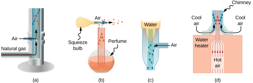
People have long put the Bernoulli principle to work by using reduced pressure in high-velocity fluids to move things about. With a higher pressure on the outside, the high-velocity fluid forces other fluids into the stream. This process is called entrainment. Entrainment devices have been in use since ancient times as pumps to raise water to small heights, as is necessary for draining swamps, fields, or other low-lying areas. Some other devices that use the concept of entrainment are shown in Figure 14.31.
Velocity measurement
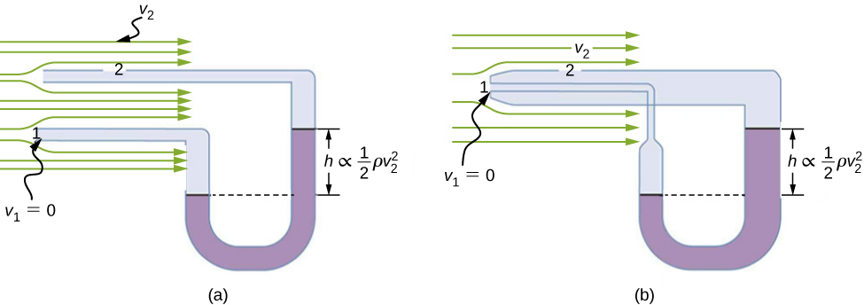
Figure 14.32 shows two devices that apply Bernoulli’s principle to measure fluid velocity. The manometer in part (a) is connected to two tubes that are small enough not to appreciably disturb the flow. The tube facing the oncoming fluid creates a dead spot having zero velocity () in front of it, while fluid passing the other tube has velocity . This means that Bernoulli’s principle as stated in
becomes
Thus pressure over the second opening is reduced by , so the fluid in the manometer rises by h on the side connected to the second opening, where
(Recall that the symbol means “proportional to.”) Solving for , we see that
Part (b) shows a version of this device that is in common use for measuring various fluid velocities; such devices are frequently used as air-speed indicators in aircraft.
A fire hose
All preceding applications of Bernoulli’s equation involved simplifying conditions, such as constant height or constant pressure. The next example is a more general application of Bernoulli’s equation in which pressure, velocity, and height all change.
Example 14.7
Calculating Pressure: A Fire Hose Nozzle
Fire hoses used in major structural fires have an inside diameter of 6.40 cm (Figure 14.33). Suppose such a hose carries a flow of 40.0 L/s, starting at a gauge pressure of . The hose rises up 10.0 m along a ladder to a nozzle having an inside diameter of 3.00 cm. What is the pressure in the nozzle?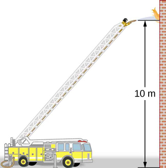
Strategy
We must use Bernoulli’s equation to solve for the pressure, since depth is not constant.Solution
Bernoulli’s equation iswhere subscripts 1 and 2 refer to the initial conditions at ground level and the final conditions inside the nozzle, respectively. We must first find the speeds and . Since , we get
Similarly, we find
This rather large speed is helpful in reaching the fire. Now, taking to be zero, we solve Bernoulli’s equation for :
Substituting known values yields